Looking for a Tutor Near You?

Post Learning Requirement » x
Ask a Question
x

Choose Country Code

x

Direction

x

Ask a Question

x

Hire a Tutor

OSI Network Model

Published in: Networking
20,664 Views

The Open Systems Interconnection [model (OSI Model) is a conceptual model that characterizes and standardizes the internal functions of a communication system by partitioning it into abstraction layers.

Prantik S / Kolkata

11 years of teaching experience

Qualification: MCA (Jaipur National University - [JNU], Jaipur - 2017)

Teaches: Basic Computer, Computer for official job, MS Office, School Level Computer, ICT Training, Computer Science, Information Practice, IT & Computer Subjects, BCA Tuition, IT, Computer, C, C++, C# (C Sharp), Java And J2EE, Python Programming, Visual Basic, BCA Subjects, Hardware Training, Networking, Java Script

Contact this Tutor
  1. OSI Application Presentation Session Transport Data Link Network Model (Basics) Application Presentation Session Tra nsport Data
  2. OSI Network Model o The Open Systems Interconnection (OSI) model began as a reference model, but has since been implemented. o It was created by the International Organization for Standardization (ISO) to provide a logical framework for how data communication processes should interact across networks.
  3. OSI Model Layers Upper Layer Lower Layer Applicatlon Presentation Session Transport Network Data Link Physical
  4. o There are 7 layers in the OSI model. Each layer is responsible for a particular aspect of data communication. o For example, one layer may be responsible for establishing connections between devices, while another layer may be responsible for error checking during transfer. o The layers of the OSI model are divided into two groups: the upper layer and lower layer. o The upper layers focus on user applications and how files are represented on the computers prior to transport. o For the most part, network engineers are more concerned with the lower layers. o It's the lower layers that concentrate on how the communication across a network actually occurs.
  5. Sender The letter is written, put in an envelope, and dropped in a mailbox. The letter is carried from the mailbox to a post office. The letter is delivered to a carrier by the post office. Hig her layers Middle layers Lowe r laye rs The parcel is carried from the source to the destination. Receiver The letter is picked up, removed from the envelope, and read. The letter is carried from the post office to the mailbox. The letter is delivered from the carrier to the post office.
  6. Application Presentation Session Transport Netyoorlv Data Link +4 r/ifr±il' Application Presentation Session Transport net'//ork Data
  7. 7) 6} Application Presentation Session Transport Network Data link Physical Data Data Data Segments Packets Frames Application Presentation Session Transport Network Dato link Physical (3
  8. Application Layer o The Application layer provides network services directly to the user's application such as a web browser, email software and Windows Explorer. This layer is said to be "closest to the user". o Protocols that operate on this layer include: TELNET, I-ITTP, FTP, TFTP, SMTP, NTP, SNMP, EDI.
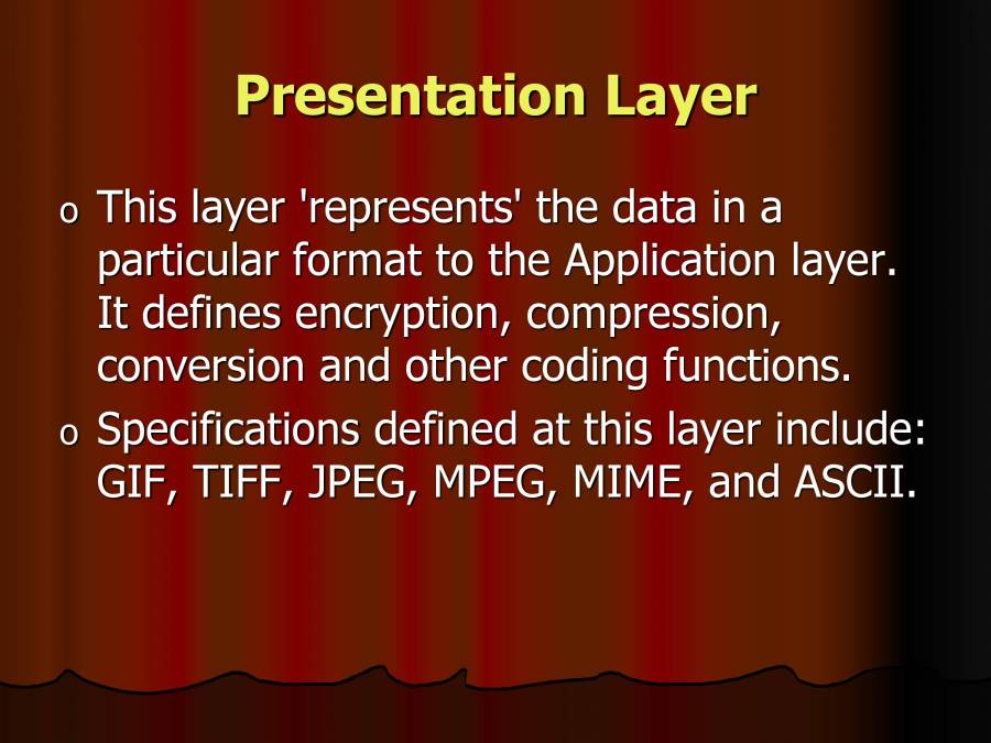
  9. Presentation Layer o This layer 'represents' the data in a particular format to the Application layer. It defines encryption, compression, conversion and other coding functions. o Specifications defined at this layer include: GIF, TIFF, JPEG, MPEG, MIME, and ASCII.
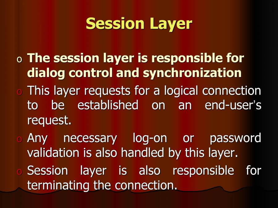
  10. Session Layer o The session layer is responsible for dialog control and synchronization This layer requests for a logical connection to be established on an end-user's reql-.leSt. Any necessary log-on or password validation is also handled by this layer. Session layer is also responsible for terminating the connection.
  11. This layer provides services like dialogue discipline which can be full duplex or half duplex. Session layer can also provide check- pointing mechanism such that if a failure of some sort occurs between checkpoints, all data can be retransmitted from the last checkpoint.
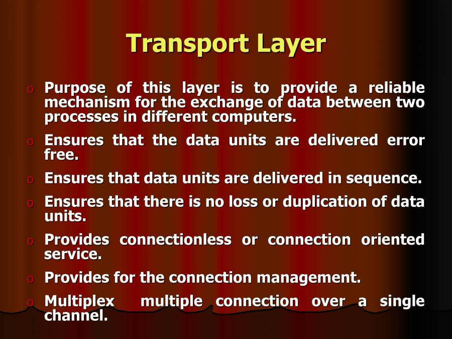
  12. Transport Layer Purpose of this layer is to provide a reliable mechanism for the exchange of data between two processes in different computers. Ensures that the data units are delivered error free. Ensures that data units are delivered in sequence. Ensures that there is no loss or duplication of data units. Provides connectionless or connection oriented service. Provides for the connection management. Multiplex multiple connection over a single channel.
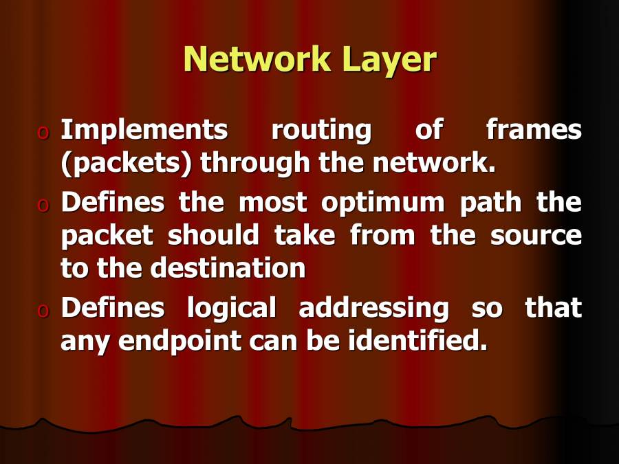
  13. Network Layer Implements routing of frames (packets) through the network. Defines the most optimum path the packet should take from the source to the destination Defines logical addressing so that any endpoint can be identified.
  14. Handles congestion in the network. Facilitates interconnection between heterogeneous networks (Internetworking). The network layer also defines how to fragment a packet into smaller packets to accommodate different media.
  15. Data Link Layer Data link layer attempts to provide reliable communication over the physical layer interface. Breaks the outgoing data into frames and the received Create and detect frame boundaries. Handle by implementing err Or S an acknowledgement and retransmission scheme.
  16. Implement flow control. Supports points-to-point as well as broadcast communication. Supports simplex, half-duplex or full- duplex communication.
  17. Physical Layer Provides physical interface for transmission of information. Defines rules by which bits are passed from one system to another on a physical communication medium. Covers all - mechanical, electrical, functional and procedural - aspects for physical communication. Such characteristics as voltage levels, timing of voltage changes, physical data rates, maximum transmission distances, physical connectors, and other similar attributes are defined by physical layer specifications.