Looking for a Tutor Near You?

Post Learning Requirement » x
Ask a Question
x

Choose Country Code

x

Direction

x

Ask a Question

x

Hire a Tutor

Using The 8251

Published in: Basic Computer
2,505 Views

Microprocessor

Sumeet S / Jaipur

8 years of teaching experience

Qualification: B.Tech + M.Tech - Electronics and Communication

Teaches: EVS, Mathematics, Science, Physics, Electronics

Contact this Tutor
  1. The Microprocessor Using the 8251
  2. RxD Gnd Txc* RxRdy 8251 0 e 10 11 12 13 14 28 27 26 25 24 23 22 21 20 19 18 17 16 15 28-pin DIP VCC RxC* DTR* RTS* DSR* Reset Clk TxD TxE CTS* SD'BD TxRdy 8251- USART Both Synchronous and Asynchronous 1. operation False start bit detection 2. 3. Automatic break detect and handling Error detection - parity, overrun and 4. framing errors. Break characters generation 5. It has built-in baud generator 6. Allows full duplex transmission and 7. reception It is compatible with extended range of 8. Intel microprocessors It is fabricated in 28 pin DIP package and all 9. its inputs and outputs are 10.TTL compatible.
  3. Refer to Fig. 3 sync 5 bils Disable Inhabit Baud Rate Factor Character Length G bits i bits Parity Check Odd Disable Stop bit Length i bit 8251 - Even Pari Mode Instruction is used only Synchronous mode Else this refers to the multiplication factor of input clock used to transmit/receive data This represents the length of each unit of information. This indicates the kind of parity bit that will be used for communication This represents the length of stop bit. The length is measured wrt the clock period. 1.5 bits means a stop bit whose duration is 1.5 clock cycles long
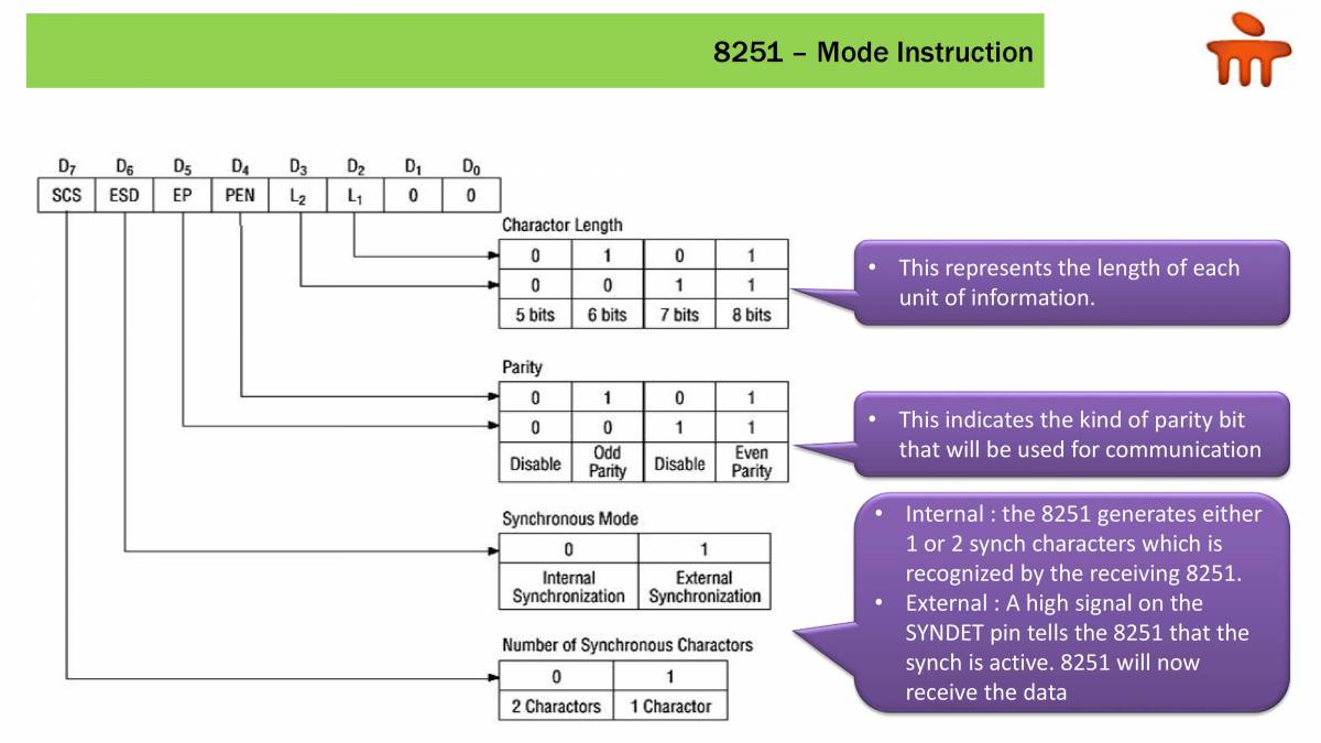
  4. scs ESD PEN Charactor Length 5 bits Parity Disable 6 bits Odd 7 bits Disable 8251 - 8 bits Even Parity Synchronous Mode Internal External Synchronization Synchronization Number of Synchronous Charactors 2 Charactors 1 Charactor Mode Instruction This represents the length of each unit of information. This indicates the kind of parity bit that will be used for communication Internal : the 8251 generates either 1 or 2 synch characters which is recognized by the receiving 8251. External : A high signal on the SYNDET pin tells the 8251 that the synch is active. 8251 will now receive the data
  5. 07 RTS SERK 02 RXE OTR 8251 - TXEN 1 ...Transmit Enable O...Disable OTR 1 —+DTR-O 1. 1 Recieve Enable Disable Sent Break Charactor -Normal Ope ration Reset Error Flag -Normal Ope rati on g-tS O —+ÄTS—I 1. 1. -Internal Reset Normal Operation -Hunt Mode (Note) Normal Ope ration Command Instruction Indicates whether 8251 will be a Tx Indicates whether data is ready for Tx Indicates whether 8251 will be a Rx Indicates whether break character has been sent Indicates whether data is ready for Rx 8251 has to be reset if Mode instruction is to be loaded again Used in Synchronous mode to look for synchronization characters
  6. 8251 - Status Word ' Indicates whether 8251 will be a Tx OSR 06 SYNDET $80 OE PE RXRDY TXROY Parity Different from TXRDY Terminal. Refer to "Explanation" ot TXROY Terminals. Same as terminaL Refer to "Expranation" ot Terminals, i 1 1 Parity Error Overrun Error Framing Error Note: Only asynchronous mode. Stop bit cannot be detected. Shows Terminal o...öSÄ-1 RXRDY: Is data ready for reading by processor TXEMPTY : Can processor write the next data to be ransmitted SYNDET/BD : Performs multiple functions The next byte is Rx before the earlier one has been read by the processor When a byte starts being read from the wrong location Indicates that device is ready to receive data
  7. ENHANCING PRODUCTIVITY THROUGH EDUCATION
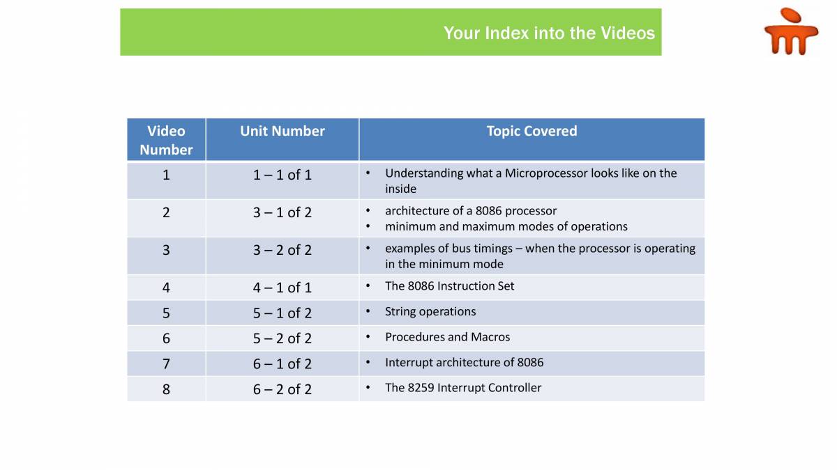
  8. Video Number 1 2 3 4 5 6 7 8 Unit Number 1— 1 of 1 3— 1 of 2 3— 2 of 2 4— 1 of 1 5— 1 of 2 5— 2 of 2 6— 1 of 2 6— 2 of 2 Your Index into the Videos Topic Covered Understanding what a Microprocessor looks like on the inside architecture of a 8086 processor minimum and maximum modes of operations examples of bus timings — when the processor is operating in the minimum mode The 8086 Instruction Set String operations Procedures and Macros Interrupt architecture of 8086 The 8259 Interrupt Controller
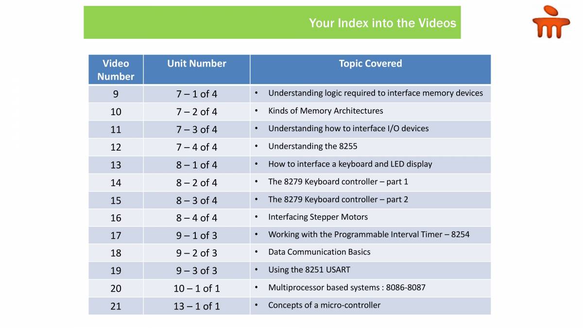
  9. Video Number 9 10 11 12 13 14 15 16 17 18 19 20 21 Unit Number 7— 1 of 4 7— 2 of 4 7—3 of 4 of 4 8— 1 of 4 8— 2 of 4 8—3 of 4 of 4 9— 1 of 3 9— 2 of 3 9— 3 of 3 10— 1 of 1 13— 1 of 1 Your Index into the Videos Topic Covered Understanding logic required to interface memory devices Kinds of Memory Architectures Understanding how to interface 1/0 devices Understanding the 8255 How to interface a keyboard and LED display The 8279 Keyboard controller — part 1 The 8279 Keyboard controller — part 2 Interfacing Stepper Motors Working with the Programmable Interval Timer — Data Communication Basics Using the 8251 USART Multiprocessor based systems : 8086-8087 Concepts of a micro-controller 8254