Looking for a Tutor Near You?

Post Learning Requirement » x
Ask a Question
x

Choose Country Code

x

Direction

x

Ask a Question

x

Hire a Tutor

Operating System- I/O Systems

Published in: Basic Computer
6,008 Views

I/O Systems in Operating System

Sumeet S / Jaipur

8 years of teaching experience

Qualification: B.Tech + M.Tech - Electronics and Communication

Teaches: EVS, Mathematics, Science, Physics, Electronics

Contact this Tutor
  1. Chapter 13: 1/0 Hardware Application 1/0 Interface Kernel 1/0 Subsystem Transforming 1/0 Requests to Hardware Operations STREAMS Performance 13.1 1/0 Systems
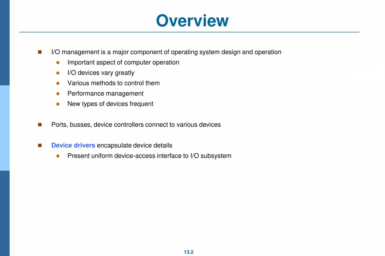
  2. Overview 1/0 management is a major component of operating system design and operation Important aspect of computer operation 1/0 devices vary greatly Various methods to control them Performance management New types of devices frequent Ports, busses, device controllers connect to various devices Device drivers encapsulate device details Present uniform device-access interface to 1/0 subsystem 13.2
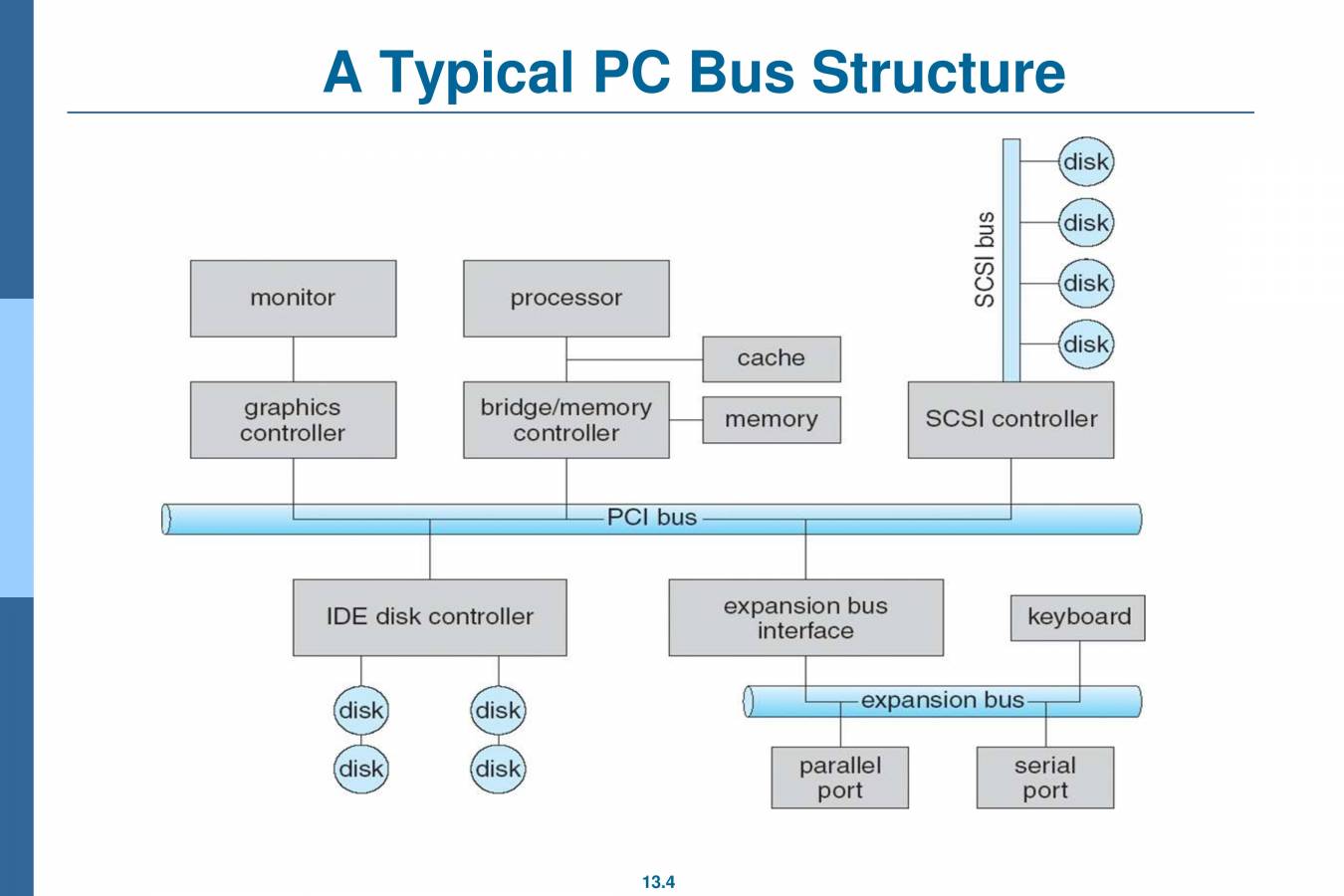
  3. Hardware Incredible variety of 1/0 devices Storage Transmission Human-interface Common concepts — signals from 1/0 devices interface with computer Port — connection point for device Bus - daisy chain or shared direct access Controller host adapter) — electronics that operate port, bus, device Sometimes integrated Sometimes separate circuit board (host adapter) Contains processor, microcode, private memory, bus controller, etc Some talk to per-device controller with bus controller, microcode, memory, etc 13.3
  4. 3 o monitor graphics controller A Typical PC Bus Structure PCI bus processor bridge/memory controller disk disk disk disk IDE disk controller cache memory expansion bus interface SCSI controller keyboard disk disk disk disk expansion bus parallel port serial port 13.4
  5. 1/0 Hardware (Cont.) 1/0 instructions control devices Devices usually have registers where device driver places commands, addresses, and data to write, or read data from registers after command execution Data-in register, data-out register, status register, control register Typically 1-4 bytes, or FIFO buffer Devices have addresses, used by Direct 1/0 instructions Memory-mapped 1/0 Device data and command registers mapped to processor address space Especially for large address spaces (graphics) 13.5
  6. Device 1/0 Port Locations on PCs (partial) 200-20F 2F8-2FF 320-32F 378-37F 3DO-3DF 1/0 address range (hexadecimal) OOO-OOF 020-021 040—043 3 FO—3 F7 3F8_3FF 13.6 DMA controller interrupt controller timer game controller serial port (secondary) hard-disk controller parallel port graphics controller diskette-drive controller serial port (primary)
  7. Polling For each byte of 1/0 2. 3. 4. 5. Read busy bit from status register until 0 Host sets read or write bit and if write copies data into data-out register Host sets command-ready bit Controller sets busy bit, executes transfer Controller clears busy bit, error bit, command-ready bit when transfer done Step 1 is busy-wait cycle to wait for 1/0 from device Reasonable if device is fast But inefficient if device slow CPU switches to other tasks? But if miss a cycle data overwritten / lost 13.7
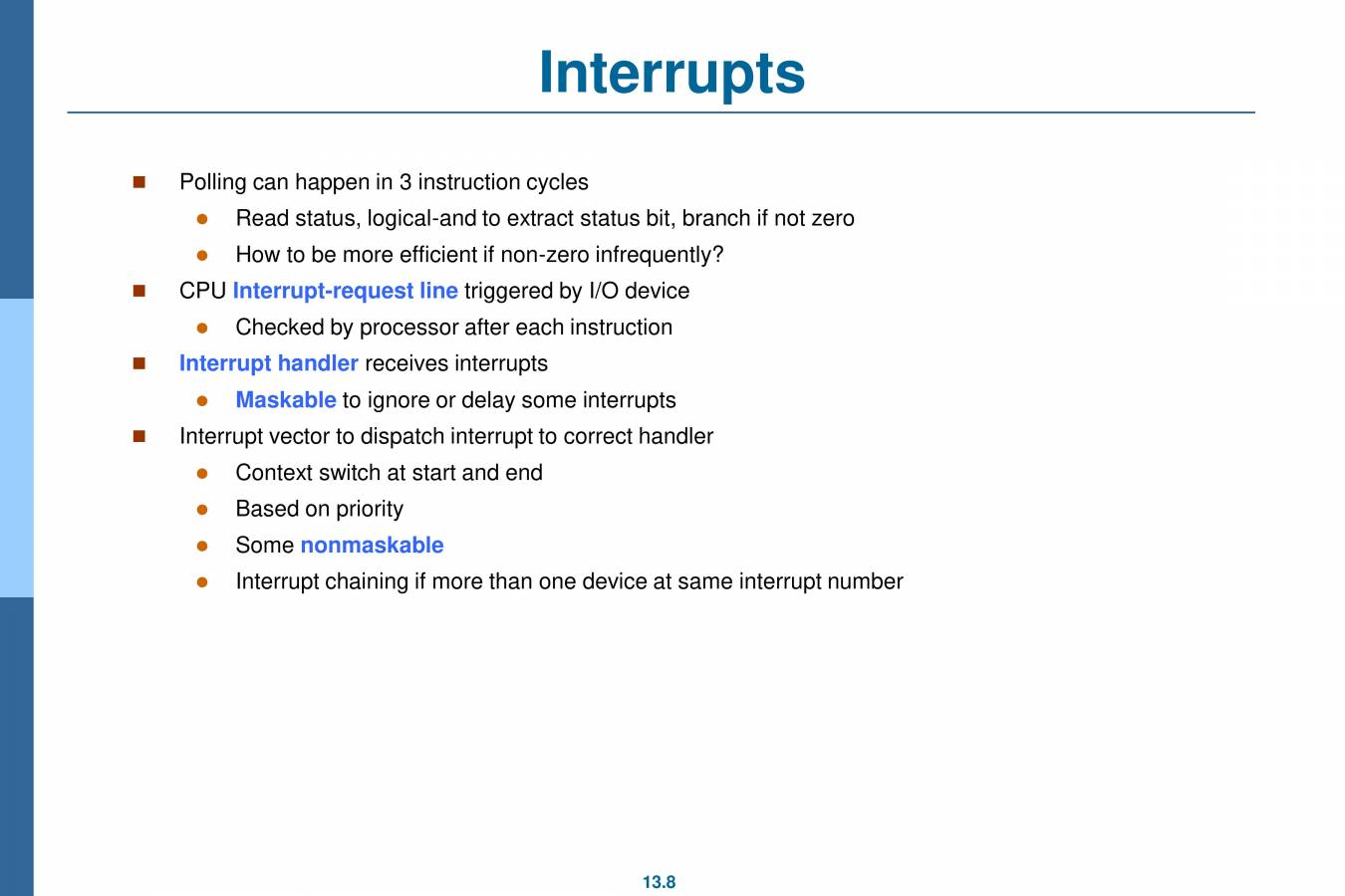
  8. Interrupts Polling can happen in 3 instruction cycles Read status, logical-and to extract status bit, branch if not zero How to be more efficient if non-zero infrequently? CPU Interrupt-request line triggered by 1/0 device Checked by processor after each instruction Interrupt handler receives interrupts Maskable to ignore or delay some interrupts Interrupt vector to dispatch interrupt to correct handler Context switch at start and end Based on priority Some nonmaskable Interrupt chaining if more than one device at same interrupt number 13.8
  9. Interrupt-Driven 1/0 Cycle CPU device driver initiates 1/0 1 CPU executing checks for interrupts between instructions CPU receiving interrupt, transfers control to interrupt handler 7 5 interrupt handler processes data, returns from interrupt 6 CPU resumes processing of interrupted task 2 4 1/0 controller initiates 1/0 3 input ready, output complete, or error generates interrupt signal 13.9
  10. Interrupts (Cont.) Interrupt mechanism also used for exceptions Terminate process, crash system due to hardware error Page fault executes when memory access error System call executes via trap to trigger kernel to execute request Multi-CPU systems can process interrupts concurrently If operating system designed to handle it Used for time-sensitive processing, frequent, must be fast 13.10
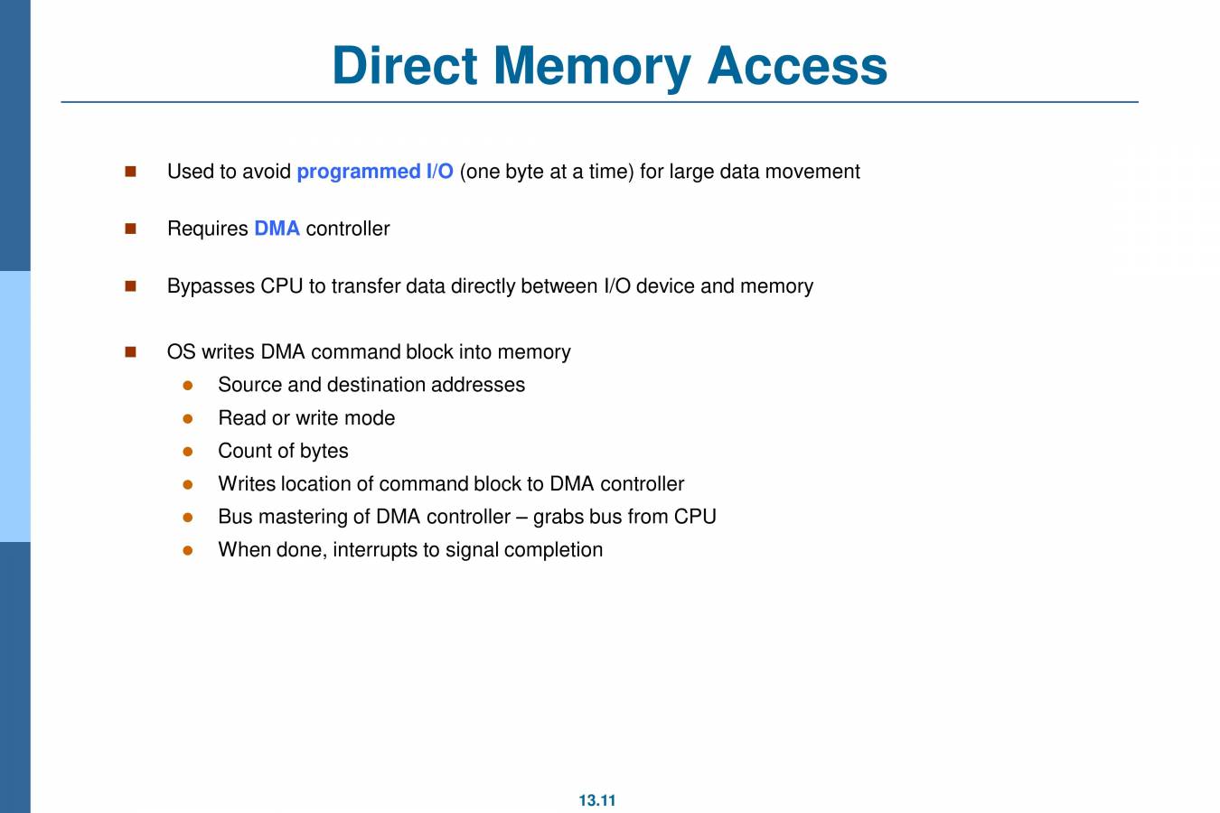
  11. Direct Memory Access Used to avoid programmed 1/0 (one byte at a time) for large data movement Requires DMA controller Bypasses CPU to transfer data directly between 1/0 device and memory OS writes DMA command block into memory Source and destination addresses Read or write mode Count of bytes Writes location of command block to DMA controller Bus mastering of DMA controller — grabs bus from CPU When done, interrupts to signal completion 13.11
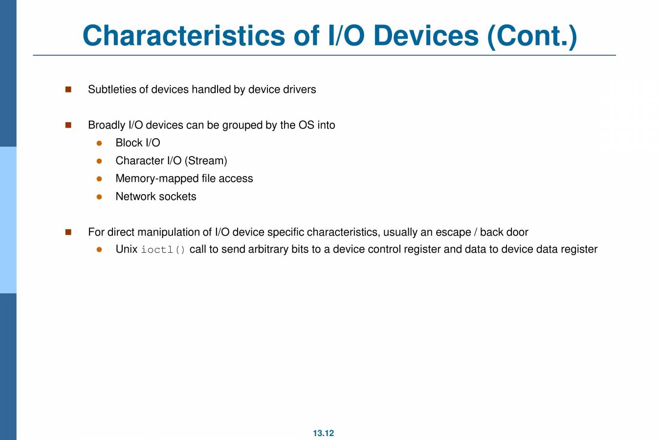
  12. Characteristics of 1/0 Devices (Cont.) Subtleties of devices handled by device drivers Broadly 1/0 devices can be grouped by the OS into Block 1/0 Character 1/0 (Stream) Memory-mapped file access Network sockets For direct manipulation of 1/0 device specific characteristics, usually an escape / back door Unix i octi ( ) call to send arbitrary bits to a device control register and data to device data register 13.12